")
Dec 4th 2024
This video shows an install on a 2005 Kenworth W900L Shout out to Fine Line Transport in Holland, MI for helping us film this video.
The unit that we are installing is our F31-1036ss-3 plug & play system. The OEM cross-reference for this unit is F31-1036-1. This unit will fit 2002 - 2007 Kenworth W900, T800, T600 trucks. To find the plug & play unit specific to your year and model truck, visit our Kenworth heater box page.
The F31-1036ss-3 includes all the parts needed to install the HVAC box on your truck. The following parts are included:
- 18 gauge stainless box
- Heater core
- Evaporator
- Thermal switch/Freeze switch
- Expansion valve
- All gaskets
- Wiring harness
- Upgraded blower motor
- Fresh air intake
- Door weldment
- O-rings
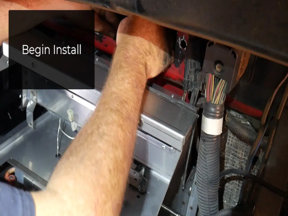
Step 1 – Begin evacuating the AC.
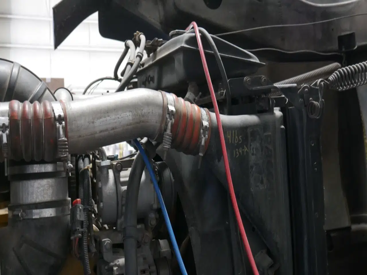
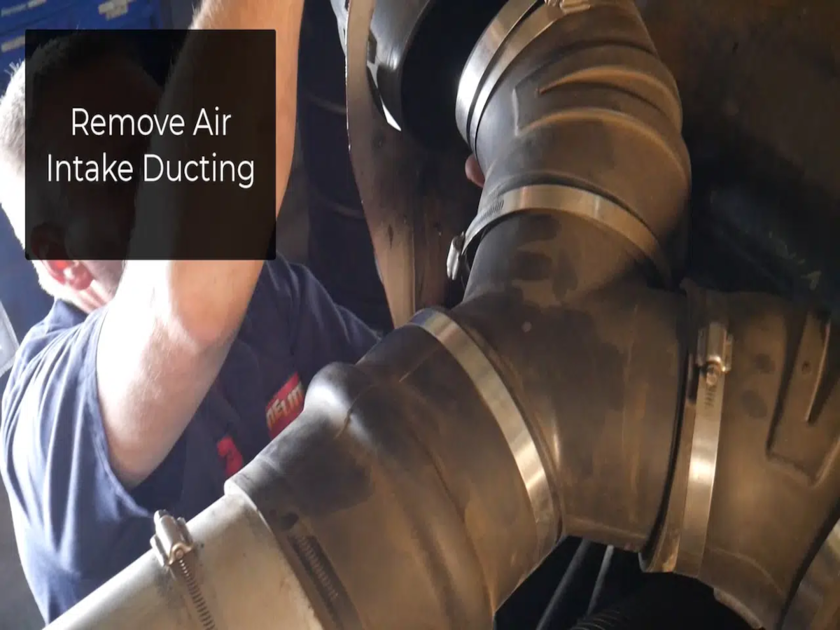
Step 2 – Remove air intake ducting.
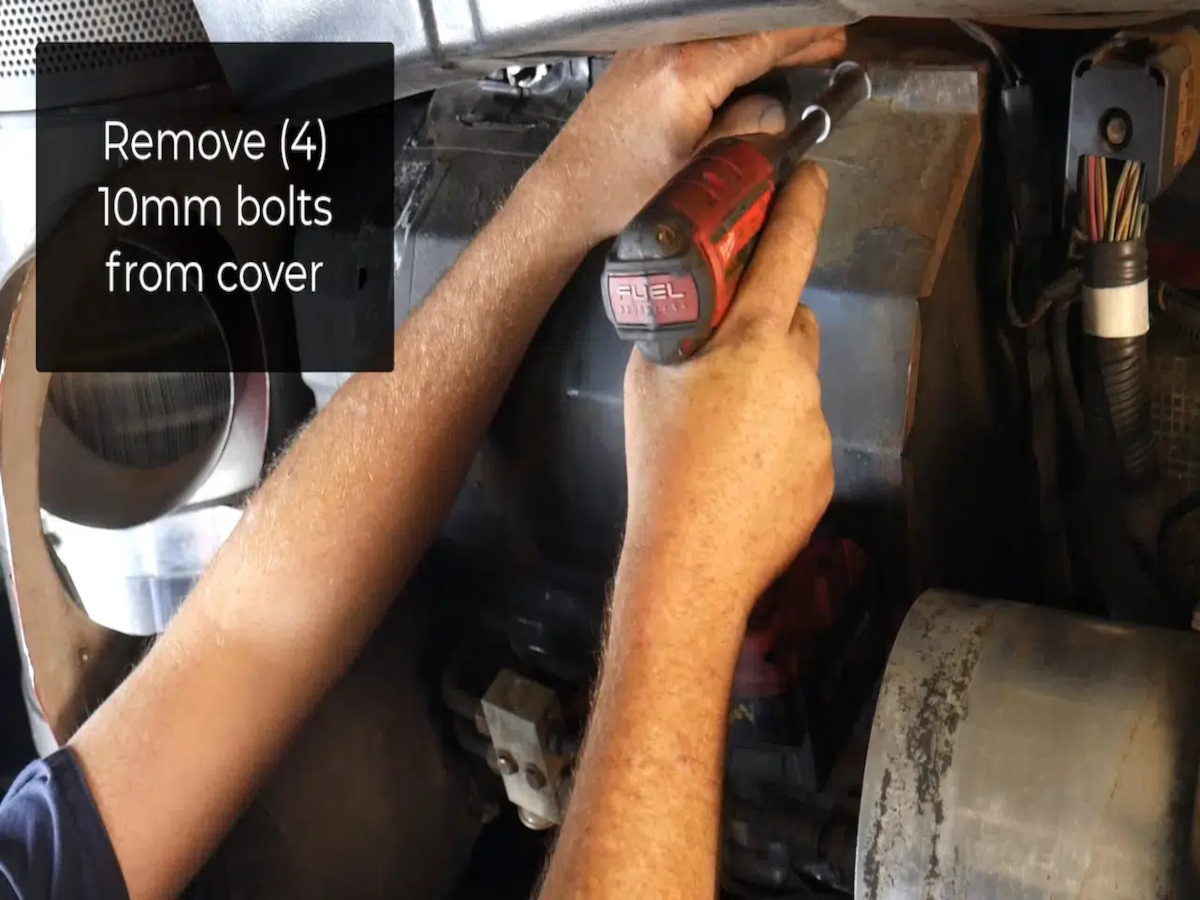
Step 3 – Remove the (4) 10mm bolts from the heater box cover.
Step 4 – Unplug the blower motor and remove the cover.
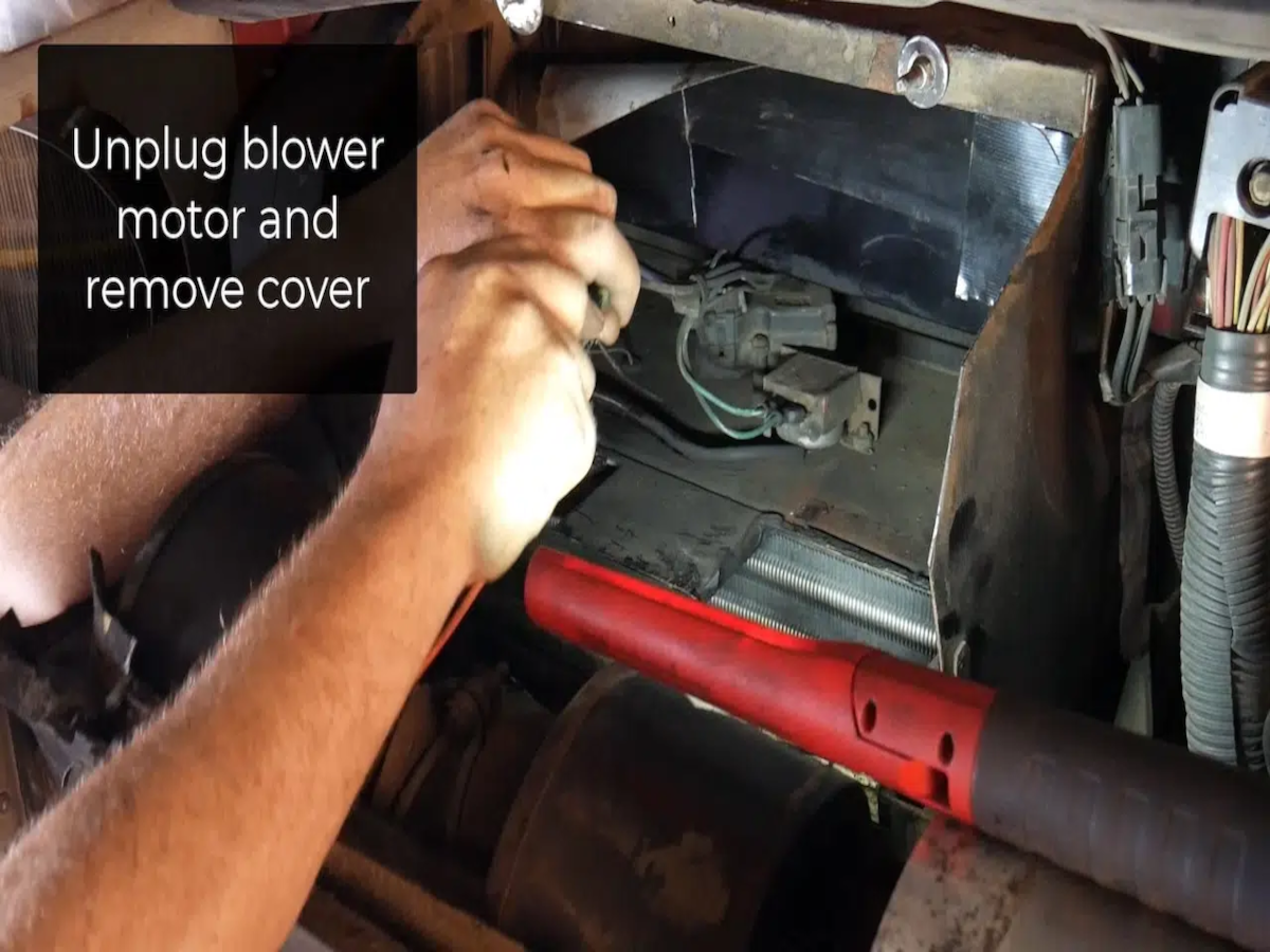
Step 5 - Unplug all the wiring from the freeze switch and actuator.

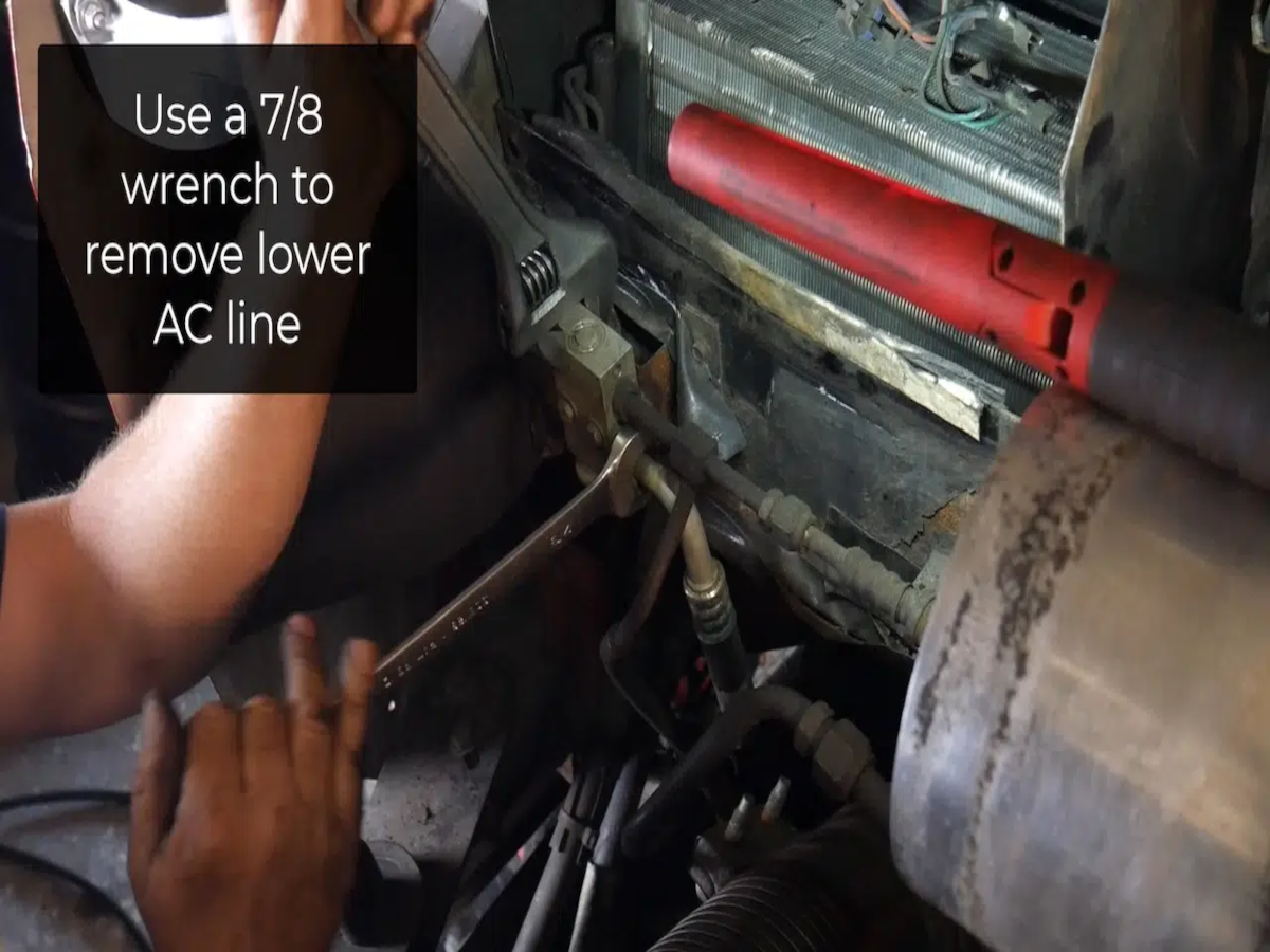
Step 6 - Remove the lower AC line using a 7/8 wrench.
Step 7 - Remove the upper AC line using a 5/8 wrench.

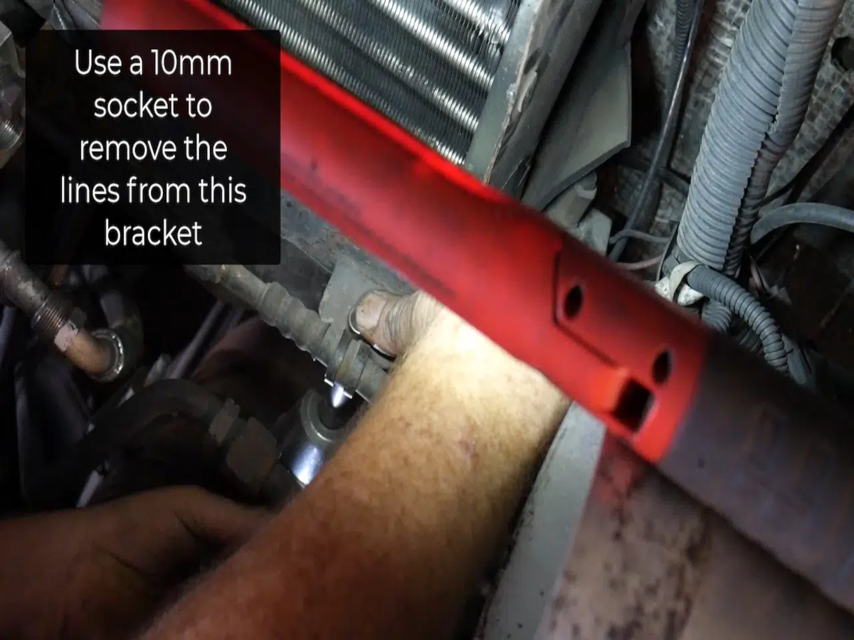
Step 8 - Remove the lines from the AC bracket using a 10mm socket and wrench.
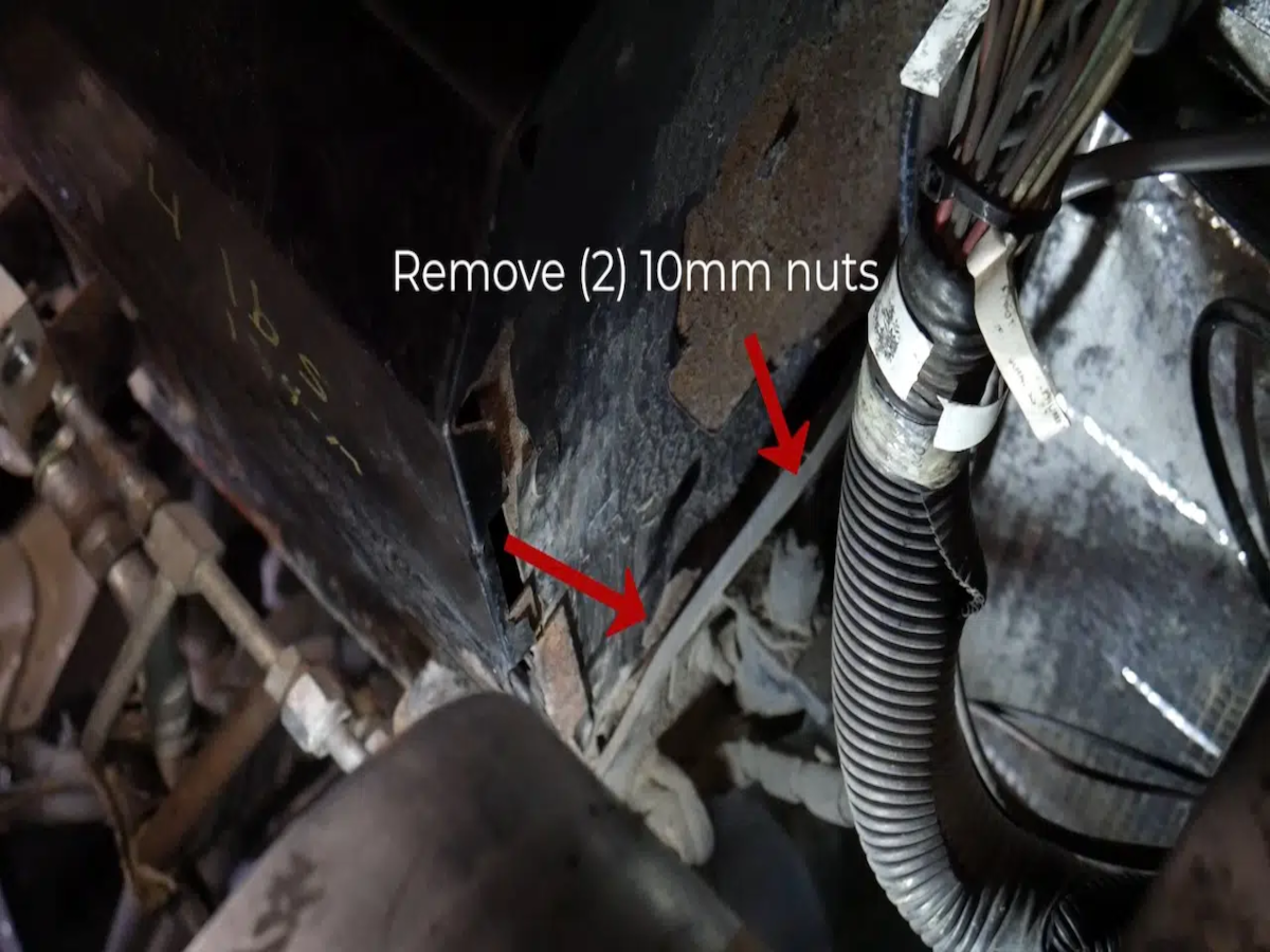
Step 9 - Remove the (2) 10mm nuts and pull the fan control solenoid from the box.
Step 10 - Remove the two bolts from the fresh air reinforcement bracket using Phillip's screwdriver.

Step 11 - Turn off the two valves that allow the coolant to run from the motor into the heater core in order to prevent the coolant from leaking. Once switched off, catch the remaining coolant using a bucket.

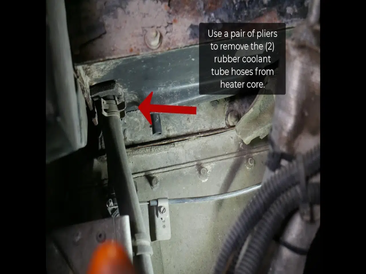
Step 12 - Remove the (2) rubber coolant tube hoses from the heater core using a pair of pliers.
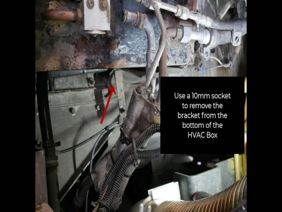
Step 13 - Remove the remaining bracket from the box using a 10mm socket.
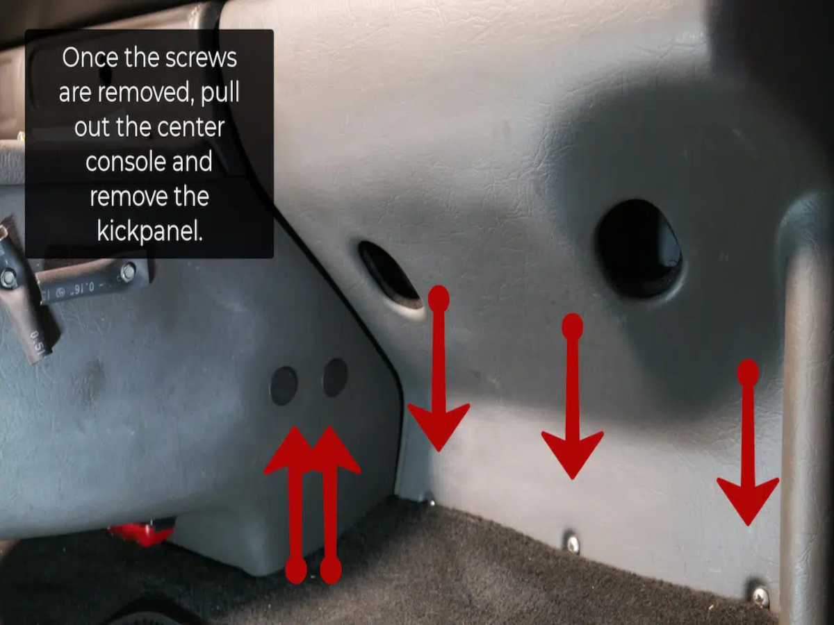
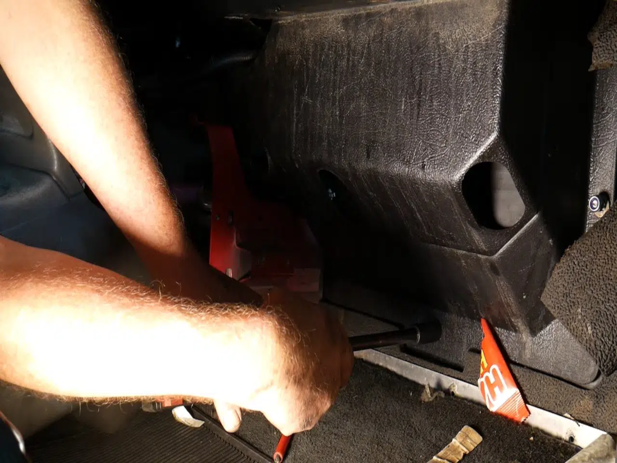
Step 14 - Remove the (7) Phillip's head screws located inside the cab of the truck in order to access a few of the bolts on the heater box. Alternatively, these screws can be located on the center console while three of the screws are on the kick plate underneath the glove box.

Step 15 - Pull out the center console and the kickpanel once the screws are out.
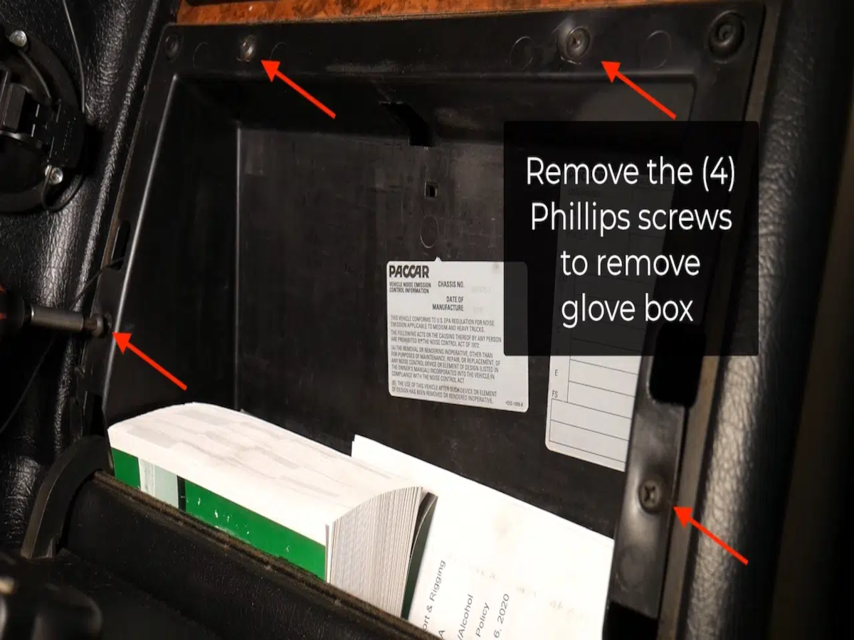
Step 16 - Remove the (4) Phillips screws to remove the glove box.
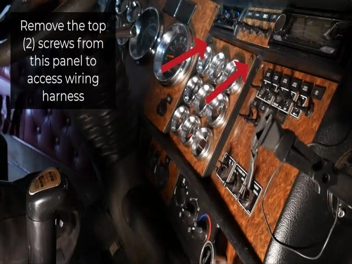
Step 17 - Remove the top (2) screws from this panel to access wiring harness.
Step 18 - Remove the bolt on the bottom and (2) center nuts using a 13mm socket.

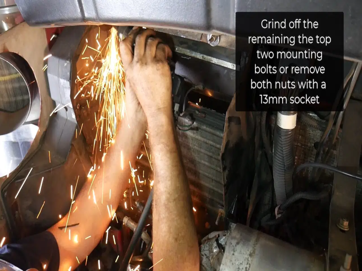
Step 19 - On the motor side, grind off the top (2) mounting bolts or remove both nuts with a 13mm socket or wrench.
Step 20 - Unplug the old wiring harness.

Step 20 B - Push down the tabs on the wiring to pull them apart.

Step 21 - Remove the old heater box from the fire wall.

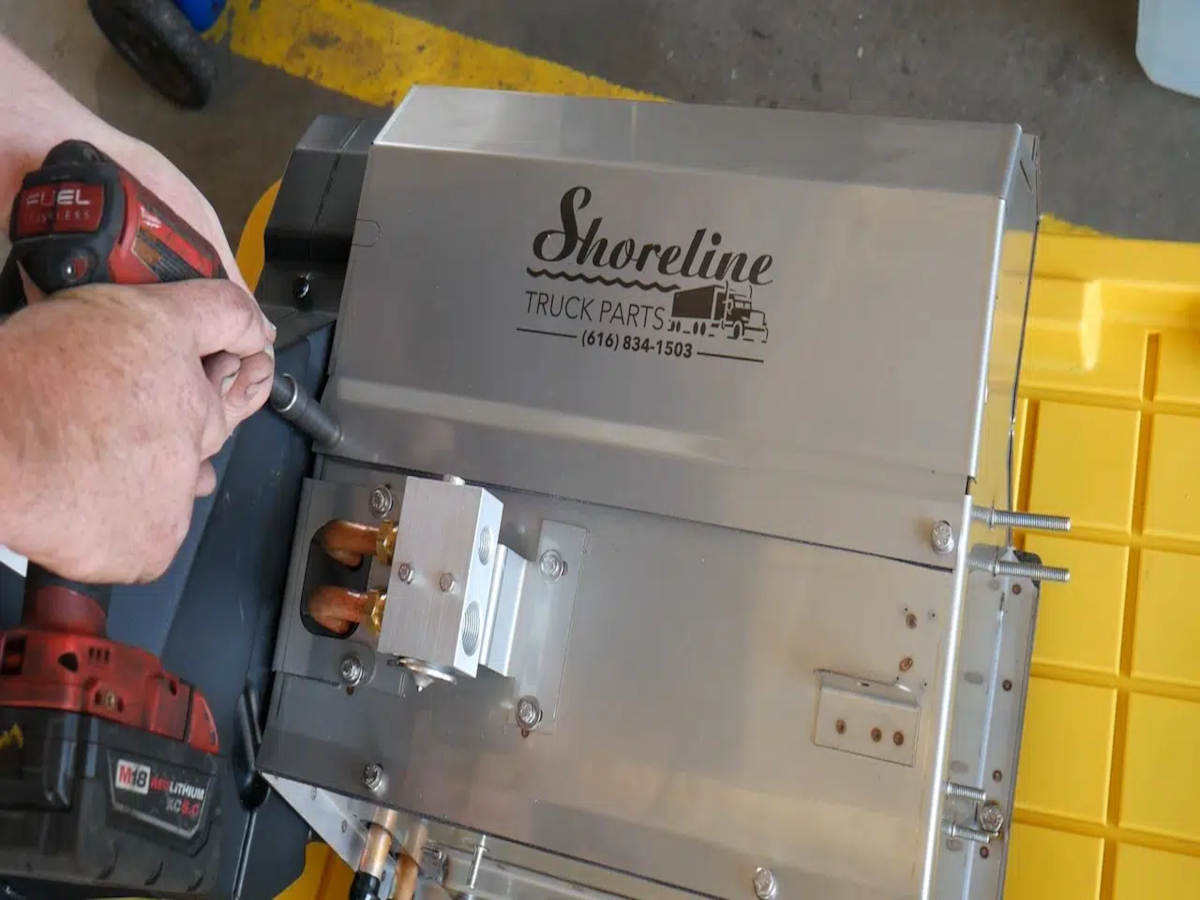
Next, we will be preparing the new Shoreline heater box for installation.

Step 22 - Take out the four bolts using a 10mm socket.
Step 23 - Unhook the blower motor from the wiring harness.

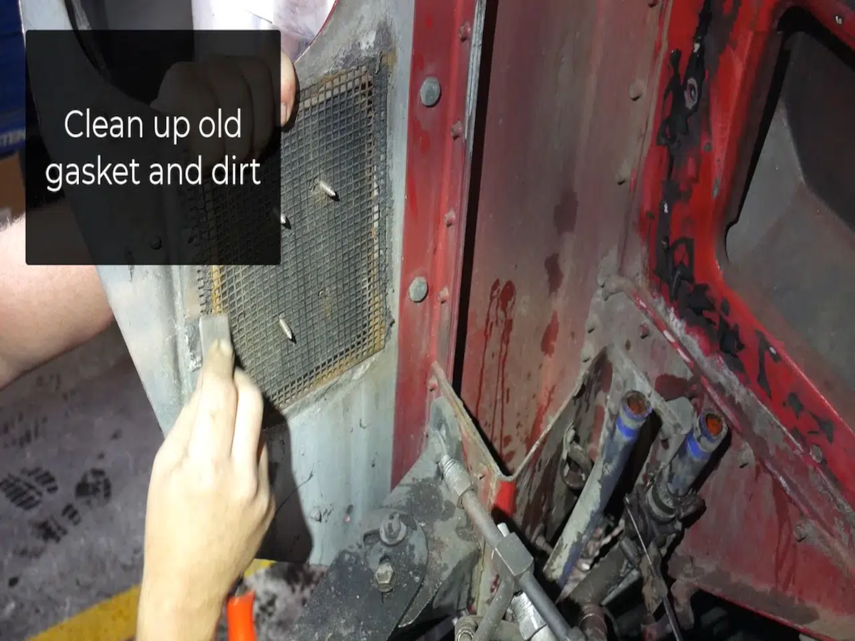
Step 24 - Install the fresh air intake gasket. Before installing the box, clean up the old gasket and the area from debris.
Step 25 - Install the new box.
Step 26 - Get the bolts and nuts started inside the cab.

Step 27 - Finish tightening the nuts and bolts inside the cab.
Step 28 - Before buttoning everything up, plug in the wiring harness.

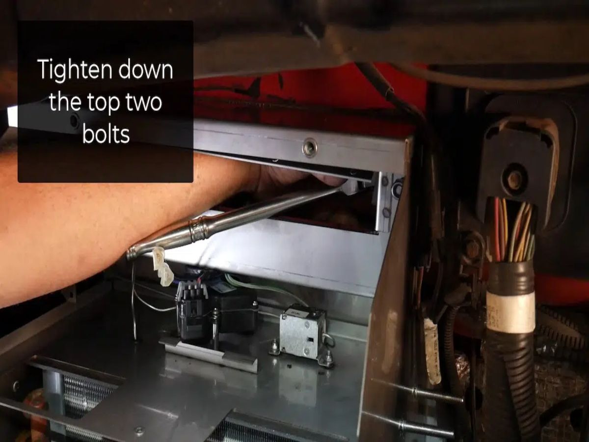
Step 29 - Moving on to the front of the truck, tighten down the top two bolts.
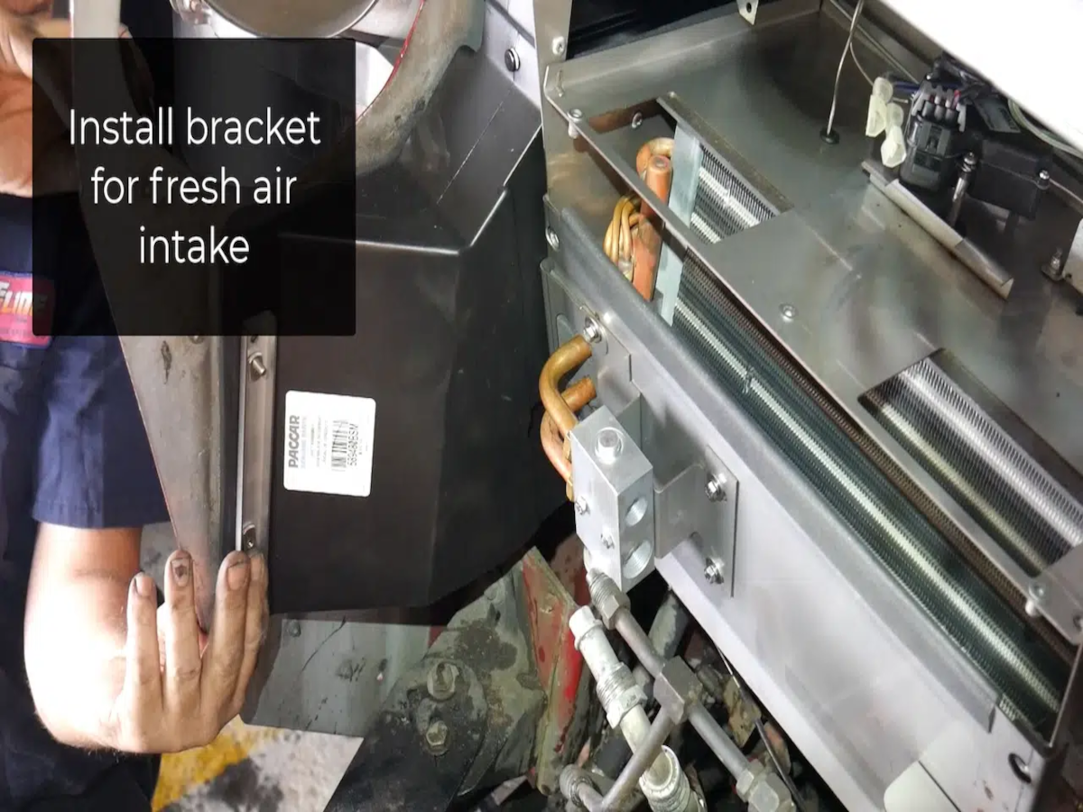
Step 30 - Install the reinforcement bracket for the fresh air intake. This bracket is included in the kit. It's stainless steel along with two stainless steel bolts.
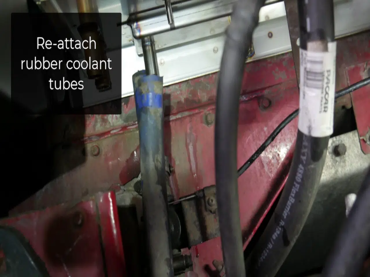
Step 31 - Re-attach the two rubber coolant tubes to the bottom of the heater box. Attach the bracket underneath the box as well.
Step 32 - Install the AC lines. Make sure to also install the supplied O rings. Install the top line first, using a 5/8 wrench.
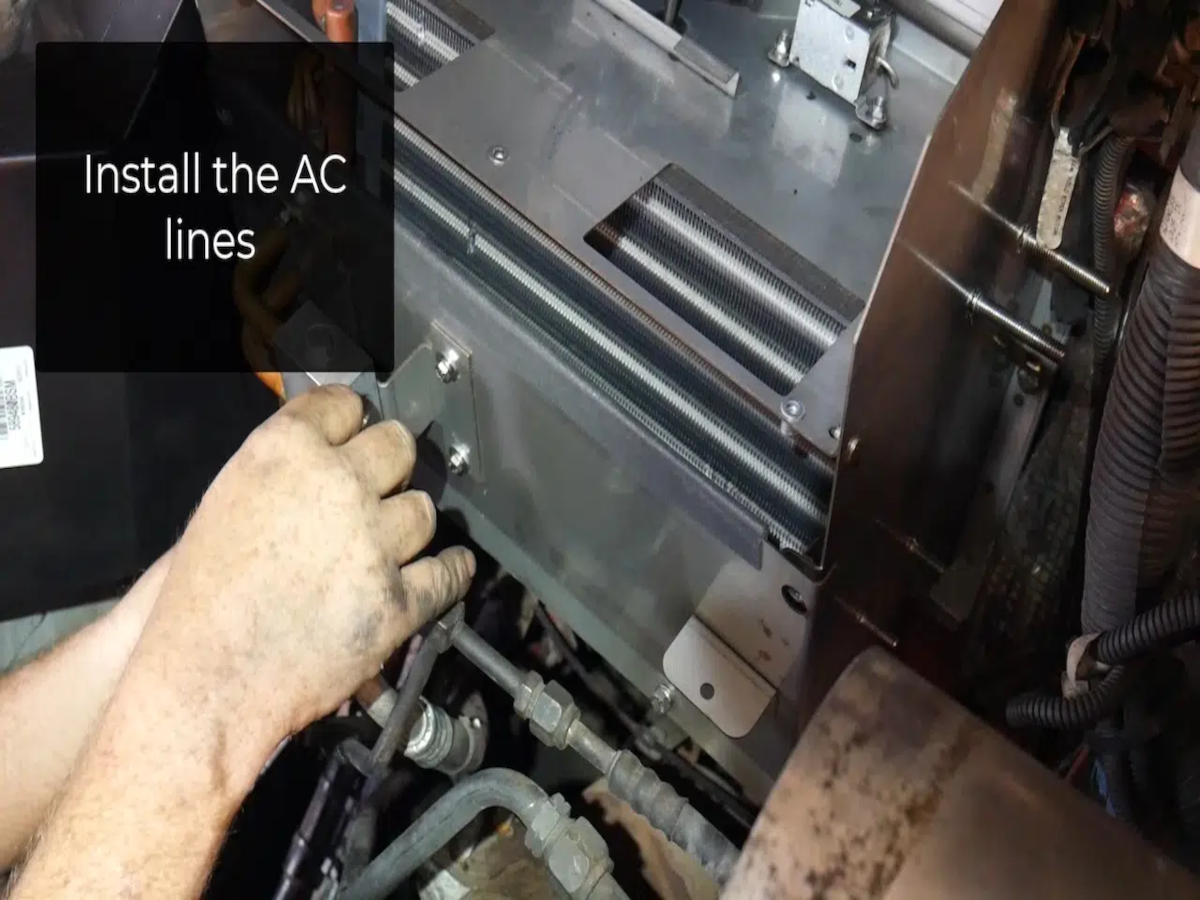
Step 33 - Use a 7/8 wrench to install the bottom line.

Step 34 - Attach the AC line to AC bracket.

Step 35 - Re-attach the fan solenoid (2) 10mm nuts.

Step 36 - Re-wire the blower motor. Make sure the black ground is connected to the black ground from the motor. The truck's hot wire is blue with a black stripe.

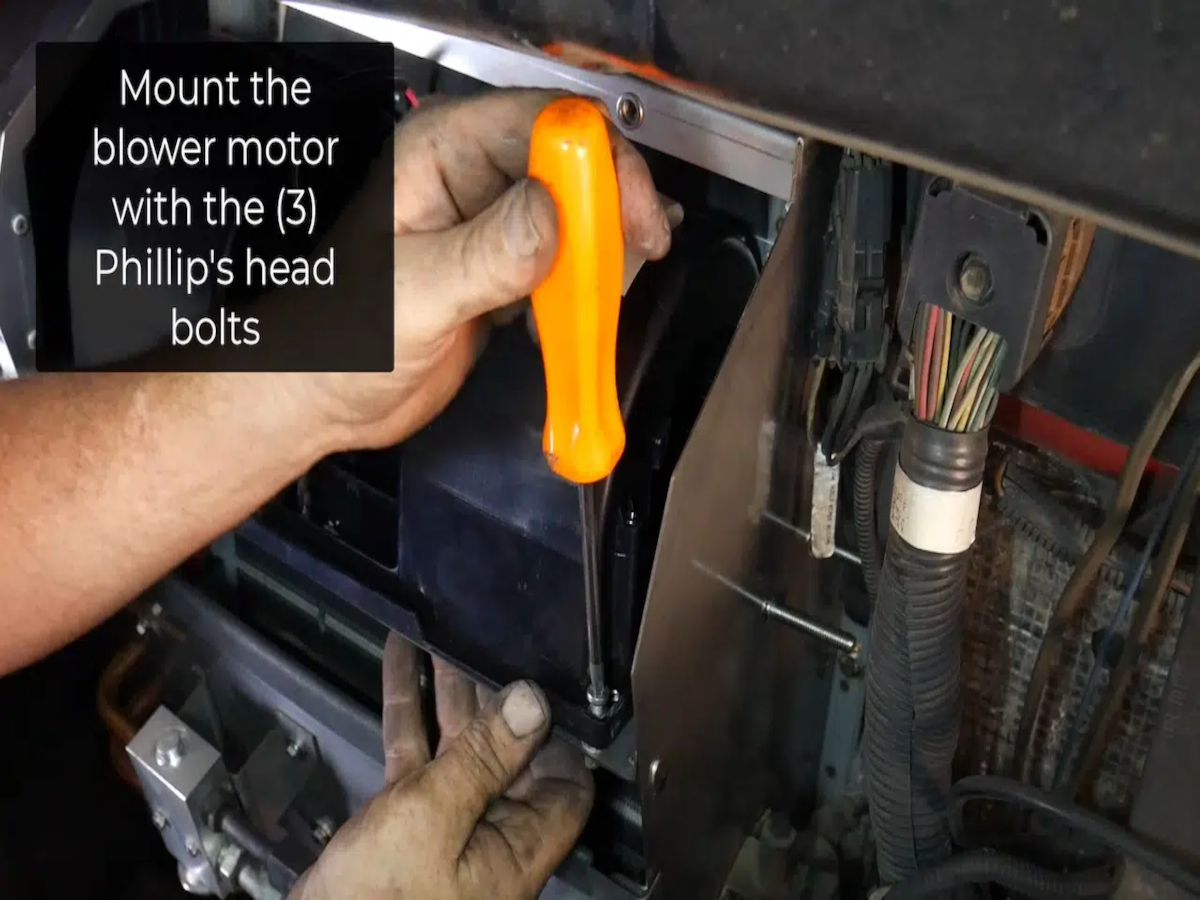
Step 37 - Mount the motor with the (3) Phillips head bolts supplied.
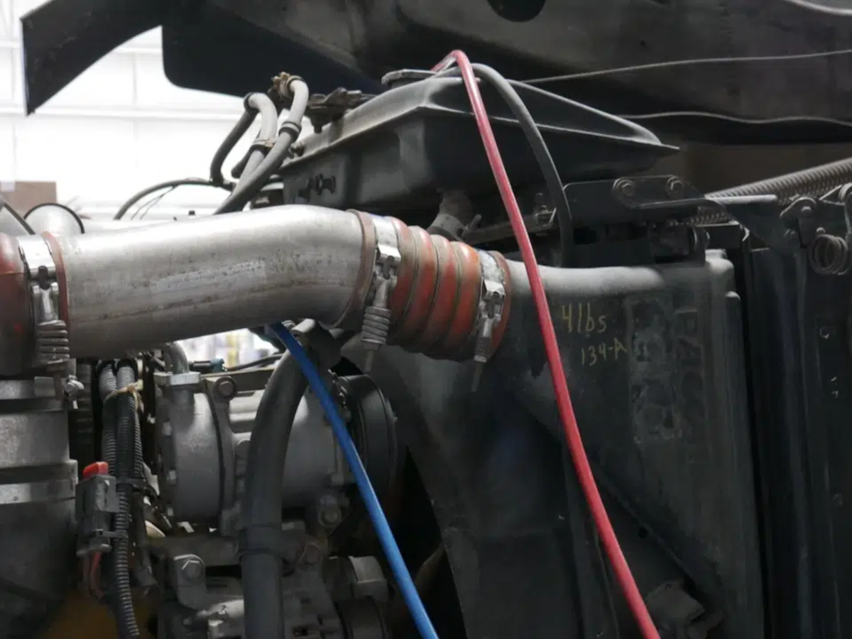
To save time, if you have an AC machine, you can start recharging it at this point.
Step 38 - Put the rest of the truck back together.
Install the lid using the (4) 10mm bolts.

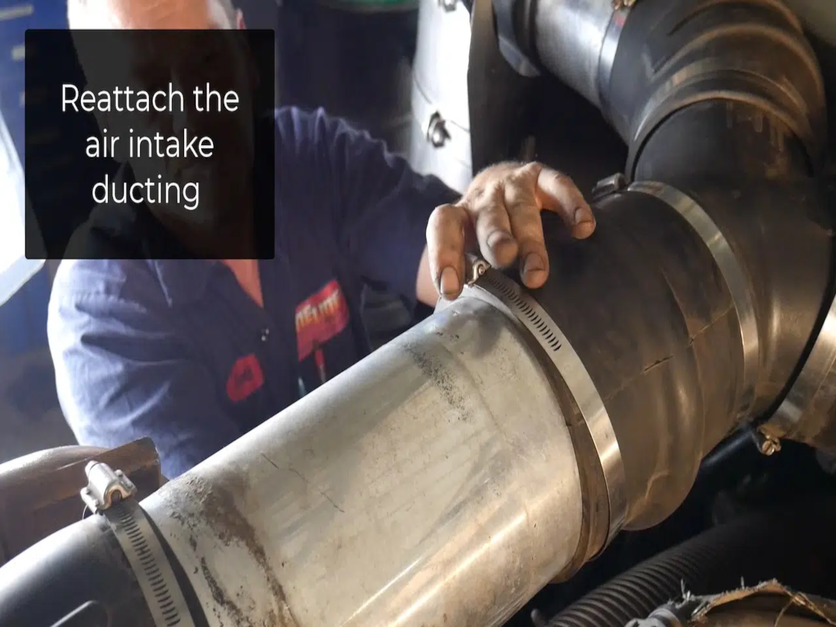
Re-attach the air intake ducting.
Re-install the center console and the kick panel with the remaining seven screws.

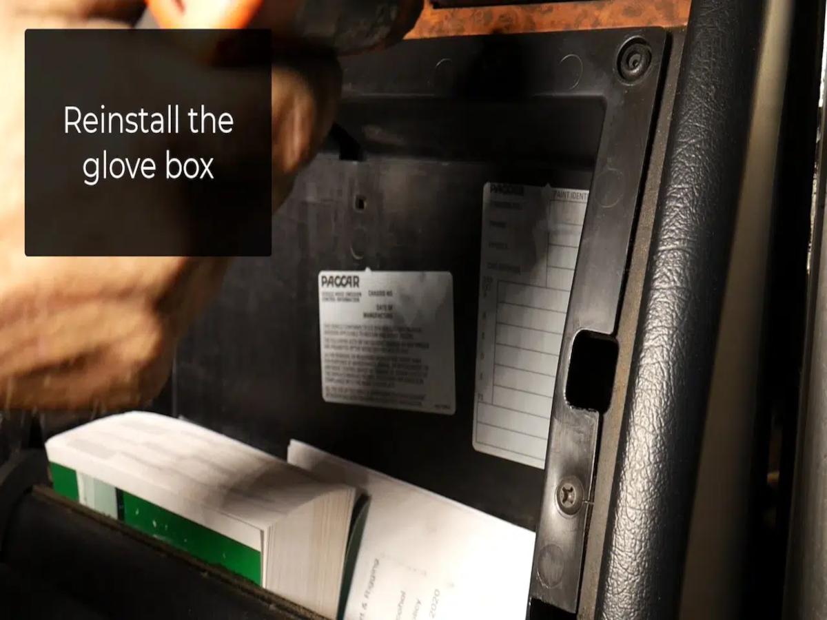
Re-install the glove box and the remaining panels.
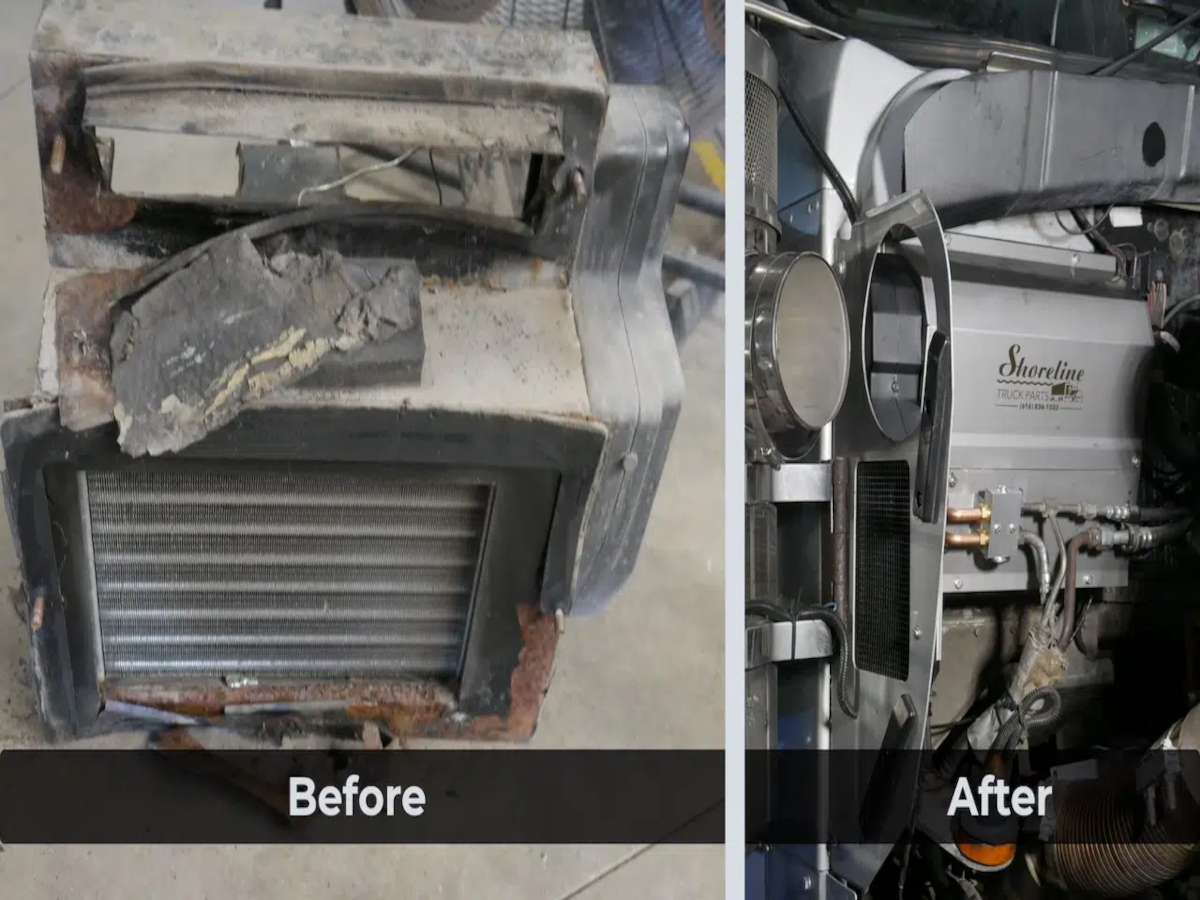
Before and After